Misinterpretation of tensile instability in SPH solid dynamics (Part 3)
Xiangyu Hu
Numerical examples
In this part, we demonstrate that the typical numerical simulations which are identified in the literature suffering from tensile instability, are numerically stable, i.e. without particle clustering, artificial fracture or zigzag stress pattern, if the non-hourglass formulation (denoted as SPH-ENOG) is employed. In the following, the numerical results obtained by the original SPH (denoted as SPH-OG) method and artificial stress (denoted as SPH-OAS) method are also given as reference.
2D oscillating plate

As shown in Fig. 3, an oscillation 2D plate with one edge fixed is considered. The length and thickness of the plate are $L$ and $H$ respectively. While the plate is assigned a initial profile of upward velocity, the left part is constrained to produce a cantilever plate.
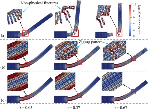
It is observed form Fig. 4 that SPH-OG leads to non-physical fractures, occurring just at the beginning of the simulation. It is also shown that SPH-OAS is able suppress the non-physical fractures, but still suffers from the zigzag patterns. Clearly, for the results obtained with non-hourglass formulation, neither non-physical fractures and zigzag patterns appear. Furthermore, the particle distribution is still uniform, and the stress profile is smooth.
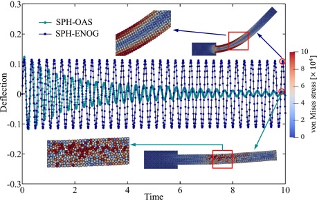
As shown in Fig. 5, the simulation has been carried out for over 30 periods. With SPH-ENOG, the deflection only decreases marginally, but the SPH-OAS exhibits rapid energy decay, thus it cannot be used for long-duration computations.
2D colliding rubber rings
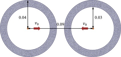
The collision of two rubber rings is simulated. As shown in Fig. 6, two rings with inner radius 0.03 and outer radius 0.04 are moving towards each other with a initial velocity. Note that, when two rings collide with each other, a significant tensile force will be generated from the stretching of the rings.
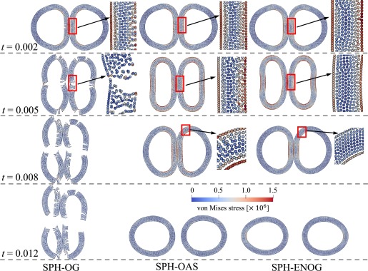
Fig. 7 shows the evolution of particle configuration for the SPH-OG, SPH-OAS and the present SPH-ENOG when the initial velocity magnitude is moderate. Clearly, the SPH-OG suffers from serious non-physical fractures at the beginning of the computation, and the calculation process can barely continue. For the SPH-OAS, the non-physical fractures can be suppressed, and the particle distribution is uniform at the initial stage. However, with the passage of time, the zigzag distribution of particle configuration and von Mises stress gradually becomes apparent. While for the SPH-ENOG, the particle and stress distribution are uniform during the whole calculation process, and the numerical instabilities can be completely eliminated.
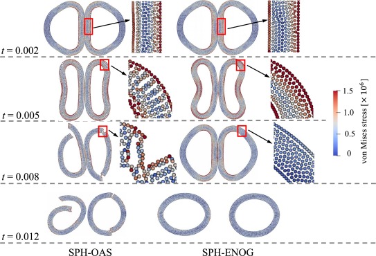
Furthermore, with the colliding velocity increased, it can be seen from Fig. 8, not only zigzag patterns, but also numerical fractures appear for results obtained by SPH-OAS. Fortunately, SPH-ENOG performs well even at large colliding velocity, and all numerical instabilities are perfectly eliminated, which suggests the stability and robustness of the present SPH-ENOG.
No tensile instability in SPH elastic dynamics?
In these two numerical examples, tensile stress is obvious due to large deformations and even dominants the dynamics, the simulations are very stable when the non-hourglass formulation is employed. Such observation at least is able to clarify that the numerical instabilities in these simulations using standard SPH formulation are not introduced by tensile instability as previously identified. Another observation is that, even the artificial stress method is not able to eliminate the hourglass modes, it can mitigate them or at least delay their development. This phenomenon is in good agreement with the idea that adding extra artificial repulsion forces in SPH generally stabilize the simulation, although they usually also introduce excessive numerical dissipation, as shown in Fig. 5, if they are not well designed.
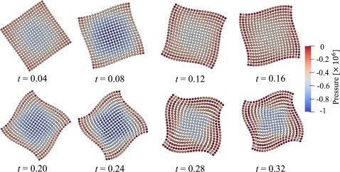
One more brave assumption is that there may be no tensile instability at all in SPH elastic dynamics. This statement may be conflict with the fluid simulations, which obviously still suffer from tensile instability even when shear stress is not taken into account. Comparing the above simulations with typical ones for fluids, one may argue that there are no dominant isotropic tension, or hydrostatic pressure, exhibit in the former. One can carry out a simple numerical experiment on this, by applying a 2D circular solid piece (with relaxed particle distribution to break exact symmetry) with initial radial velocity and check if SPH-ENOG can still give a stable simulation. If the simulation is proved to be not stable, one may need to rename tensile instability into negative-pressure instability. Otherwise, there is no tensile instability in SPH elastic dynamics at all!
While I am happy to see this simulation result using SPHinXsys, I would predict the second as in the journal paper there is already a case (spinning plate as shown below) is quite similar to the one mentioned above.
